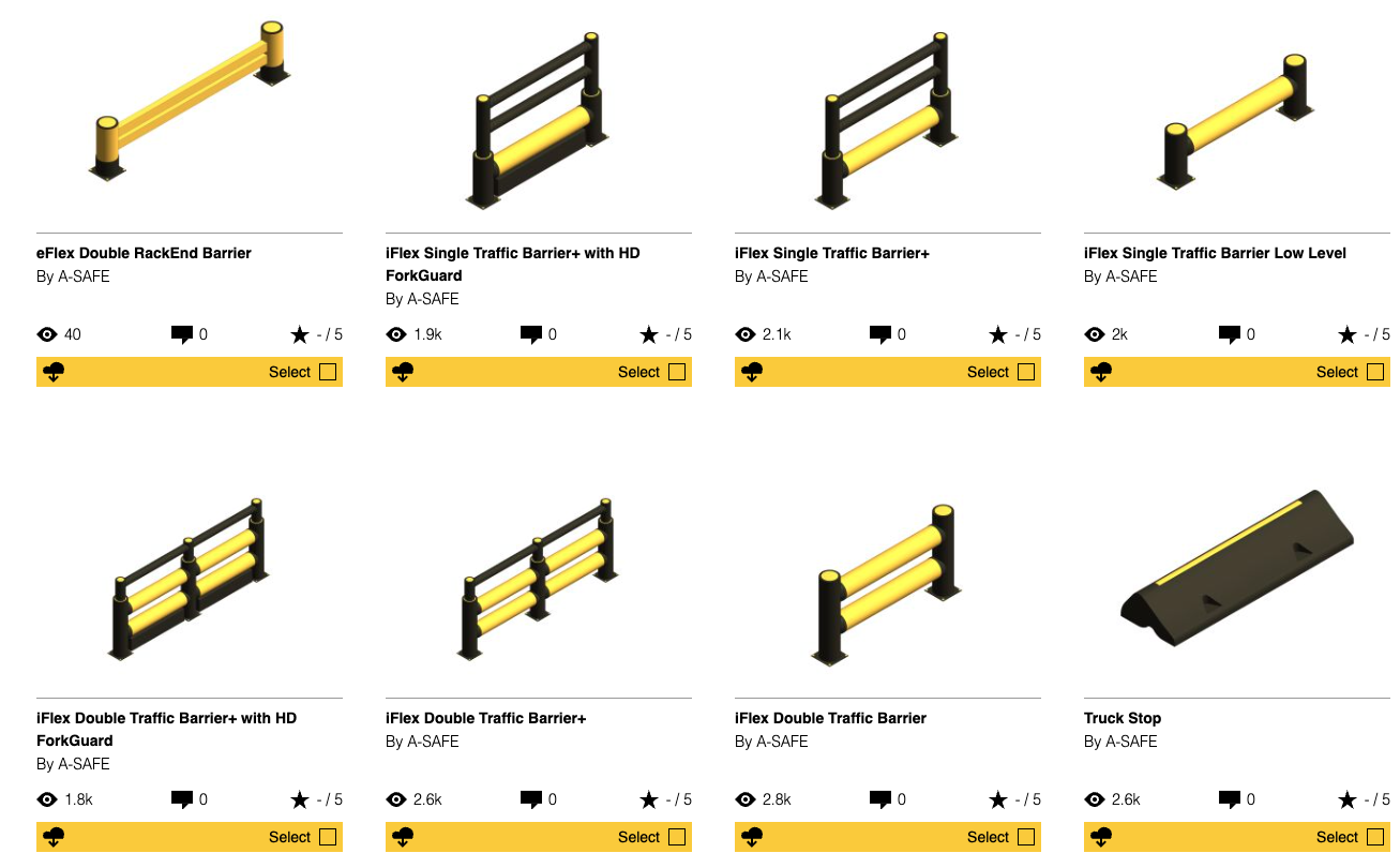
DOWNLOAD YOUR ASSETS TODAY
Manufactured by A-SAFE
Architects, designers, and engineers often need a clean specification to include protective barrier systems into a new site plan, before any vendor is selected.
This page provides an architectural specification for a modular, energy-absorbing polymer safety barrier system used to separate people, vehicles, and equipment in mixed-traffic environments. The specification language is written in CSI 3-part format and includes performance criteria aligned with PAS 13 and relevant ASTM and ISO standards.
If you are looking for BIM and CAD assets (Revit families, CAD blocks, typical details) to support your drawings, you can request or download them below.

Need BIM objects or CAD blocks for your drawings?
A-SAFE provides coordinated resources to support design intent and construction documentation:
-
Revit families (select barrier types)
-
CAD blocks (2D and typical details)
-
Typical layouts and clearance guidance
-
Anchorage detail templates by substrate condition
-
Submittal packages for tender review

Common searches this spec supports
-
PAS 13 polymer safety barrier specification
-
20 kJ impact rated vehicle barrier
-
CSI 34 71 13 vehicle barriers specification
-
CSI 10 26 16 bumper guards polymer
-
ASTM E84 Class A polymer barrier
-
UV stable safety barrier ISO 4892-3
-
Chemical resistant barrier ISO/TS 10358
-
Energy-absorbing pedestrian protection barrier system
Get the Correct Barrier Into The Plan Set Early
If you are developing a new site layout, send a plan or a basic traffic flow and we can help identify barrier runs, gates, and high-risk intersections to support your drawing set.
Quick spec summary
Basis of Design
Modular, energy-absorbing polymer safety barrier system including rails, posts, anchors, accessories, and related hardware.
Typical application areas
Industrial and logistics environments with mixed pedestrian and vehicular interaction. Suitable for new construction and retrofit installations.
Performance at a glance
-
Dynamic-impact resistance: minimum 20 kJ at 90° impact angle, tested to PAS 13 Annex C
-
Permanent deflection: max 3% of original height after 60 minutes
-
Operating temperature range: -10°C to +50°C
-
UV stability: ΔE ≤ 3 after 1000 hours exposure (ISO 4892-3)
-
Chemical resistance: rated Excellent to fuels, hydraulic fluids, de-icing chemicals, salts, common acids/alkalis (ISO/TS 10358)
-
Fire performance: ASTM E84 Class A (as specified)
Specification content
H2: PART 1 – GENERAL
H3: 1.1 Summary
A. Work includes
Provide polymer safety barriers consisting of modular rails, posts, anchorage, fixings, accessories, and required hardware to create a physical separation and impact-attenuating boundary between vehicles and people.
B. Work includes layout and coordination
Provide shop drawing layouts indicating barrier runs, post spacing, anchorage locations, clearances, and interfaces with slab edges, columns, doors, and pedestrian routes.
C. System suitability
Systems shall be suitable for new construction and retrofit and shall be designed to manage impact energy through controlled deflection and return-to-alignment behavior.
H3: 1.2 References
Comply with the latest published versions of the following, unless noted otherwise:
-
PAS 13:2017 Code of Practice for Safety Barriers in Industrial Workplaces
-
OSHA 29 CFR 1910 General Industry Standards
-
ASTM D256, ASTM D638, ASTM D790 (plastic material properties testing)
-
ASTM E84 (surface burning characteristics)
-
ISO 4892-3 (UV exposure testing for plastics)
-
ISO/TS 10358 (chemical-resistance classification for plastics)
-
ISO 9001 and ISO 14001 (management systems)
H3: 1.3 Submittals
Provide the following:
-
Product data including polymer formulation summary, mechanical properties, and dynamic-impact test reporting
-
Shop drawings indicating barrier type(s), post spacing, anchorage details, and clearance envelopes
-
Certificates demonstrating third-party witnessing or verification of dynamic-impact performance to PAS 13
-
ISO 9001 and ISO 14001 certificates
-
Installation instructions and O&M guidance including inspection intervals and recommended maintenance
H3: 1.4 Quality Assurance
-
Testing: Dynamic-impact testing shall be witnessed and certified by an independent accredited laboratory.
-
Installer qualifications: Installer shall be trained by the manufacturer and have completed similar projects in heavy-traffic or high-risk environments.
H3: 1.5 Delivery, Storage, and Handling
Deliver components in original packaging. Store indoors, elevated, and protected from UV exposure, temperature extremes, and petroleum-based chemicals until installation.
H3: 1.6 Warranty
Provide a standard manufacturer warranty covering materials for one year. Extended coverage may be offered where the owner participates in the manufacturer’s recommended installation and inspection program.
H2: PART 2 – PRODUCTS
H3: 2.1 Manufacturers
A. Basis of design
Polymer safety barrier system meeting the performance and material requirements of this section.
B. Substitutions
Substitution requests must demonstrate compliance with all performance criteria and provide comparable test evidence prior to bid close (per Division 01 requirements).
H3: 2.2 Materials
-
Rails and posts: Energy-absorbing polymer (copolymer elastomer blend) with performance characteristics suitable for repetitive impact environments.
-
Couplings/joints: Engineered polymer joints designed to manage deflection and return system alignment after impact.
-
Baseplates: Corrosion-resistant plated steel or stainless steel baseplates with verified salt-spray performance.
-
Fasteners/anchors: Stainless steel or high-strength corrosion-resistant fixings sized to substrate and design loads.
-
Color: High-visibility safety yellow (RAL 1003) unless otherwise specified.
-
Recyclability: Polymer components shall be recyclable at end of service life.
H3: 2.3 Components
Provide components as required for the application:
-
Single, double, or triple rail barrier modules (typical module lengths up to 2400 mm)
-
Posts with replaceable design that allows individual post replacement without disturbing adjacent anchors
-
Anchors suitable for substrate type and thickness (mechanical or adhesive, per design)
-
Accessories including gates, removable sections, corners, column protection, signage brackets, and end-of-run protection, supplied as a coordinated system
H3: 2.4 Performance Requirements
Barrier system shall meet or exceed:
-
Dynamic-impact resistance: Minimum 20 kJ at 90° without post fracture or anchor failure, tested to PAS 13 Annex C
-
Permanent deflection: Maximum 3% of original height 60 minutes after design impact
-
Temperature range: -10°C to +50°C
-
Chemical resistance: “Excellent” classification for fuels, hydraulic fluids, de-icing chemicals, salts, and common acids/alkalis per ISO/TS 10358
-
UV stability: Color change ΔE ≤ 3 after 1000 hours exposure per ISO 4892-3 cycle requirements
-
Surface resistivity: 10¹⁰ to 10¹² Ω where static dissipation is required
H3: 2.5 Fabrication
Manufacture components to required tolerances. Provide smooth, uniform surfaces free of sharp edges, voids, burrs, and defects. Rails and posts shall be produced without welded seams.
H2: PART 3 – EXECUTION
H3: 3.1 Examination
Verify site conditions prior to drilling and anchoring. Confirm substrate suitability and coordinate installation zones and clearance envelopes with the project team.
H3: 3.2 Preparation
-
Clean substrate to remove dust, debris, and contaminants.
-
Identify embedded services prior to drilling.
-
Where required, use scanning methods to reduce risk of reinforcement conflicts.
H3: 3.3 Installation
Install the barrier system in accordance with manufacturer instructions and approved shop drawings:
-
Drill to specified diameter and depth.
-
Install anchors using manufacturer torque guidance.
-
Set rails level and posts plumb within project tolerances.
-
Provide expansion allowance for thermal movement in long runs as required.
H3: 3.4 Field Quality Control
-
Verify anchor torque, rail alignment, post spacing, and clearances using an inspection checklist.
-
Where specified, conduct proof testing on a representative sample of anchors in each area.
H3: 3.5 Adjusting and Cleaning
Replace damaged or improperly installed components. Clean the installation area and remove packaging.
H3: 3.6 Protection
Protect barriers from construction traffic until Substantial Completion.
(Execution requirements aligned to the source architectural specification.


Contact our safety experts today for your free, no-obligation consultation